-
-
July 11, 2018 at 9:42 am
TimFethke
SubscriberHi,
I need to connect different parts for a project, and I noticed that there are 2 options. One is using the bonded contact region and one is using the fixed joint. Both can be used for surfaces so I am wondering what the exact difference is. I've done a test by connecting two parts and then calculating some modes (as I need to do modal analysis) and compared the connection methods to see if the result would be the same, but it is not.
I did find this through Ansys help:
Bonded: This is the default configuration and applies to all contact regions (surfaces, solids, lines, faces, edges). If contact regions are bonded, then no sliding or separation between faces or edges is allowed. Think of the region as glued. This type of contact allows for a linear solution since the contact length/area will not change during the application of the load. If contact is determined on the mathematical model, any gaps will be closed and any initial penetration will be ignored. [Not supported for Rigid Dynamics. Fixed joint can be used instead.]
The last line indicates that both can be used for similar purpose but that bonded contact region is not supported for Rigid Dynamics.
Can someone explain to me what the exact difference is?
-
July 11, 2018 at 12:44 pm
peteroznewman
SubscriberHi Tim,
For solid bodies that share a face and need to be "glued" together, there are ways to achieve that connection that is neither bonded contact nor fixed joint. You can use "Shared Topology" and have the elements on each side of the coincident faces share nodes. The benefit of this is a smaller model. You can get the same effect with Node Merge if each face has mesh controls to force the nodes to line up. Shared topology does this automatically.
Imagine two tubes that are placed end-to-end and the annular faces need to be connected. Bonded contact puts elements between individual nodes over the whole face and creates a very localized connection. Say the other end of one tube is a fixed support and the far end of the other tube has a lateral load so the tube is a cantilevered beam and some bending occurs. In the annular ring, the force is transmitted locally all around the face. Depending on the contact formulation, you can get some penetration of nodes into the target surface. That doesn't happen with the shared topology method.
A fixed joint creates a point at the centroid of the faces, and builds a spider of elements out to all the nodes on each face. All the forces and moments go through that one point. That is one of the benefits of using a joint, you can easily extract those quantities from your model. But there is no local node-to-node forces transferred around the annular face. The force has to go down the spider, though the point and back out on another spider to get to the other side.
There is a danger when creating joints in Mechanical. Never use duplicate on a joint in the Outline to make another joint to use elsewhere in the model because the point that was created for the first joint is used in the new joint, rather that being updated to the location of the new faces. That means the invisible spiders that are created can go from one of the new faces, all the way over to a point on the other side of your model through a point, and then all the way back. You can imagine that a small tension on the tubes of the new joint will have a result that includes a HUGE moment, and a small force, when it should have a zero moment. This can cause the solver to have convergence difficulties. This kind of mistake cannot happen with bonded contact.
When there is a significant gap between the faces that need to be "glued together", the fixed joint will always work by simply choosing the two faces, but bonded contact may not create any contact elements and the bodies will not be glued. The corrective action is to type in a Pinball radius to make sure that the contact elements are created. You should always insert the Contact Tool and Generate Initial Contact Status before you start the Solver. You don't need to to that for Fixed Joints.
Regards,
Peter -
July 11, 2018 at 3:48 pm
-
July 11, 2018 at 6:55 pm
peteroznewman
SubscriberPainful experience Tim; I still get burned occasionally : )
I once used a joint to represent a long lead screw between two faces that were far apart. Got burned on that because of huge moments. The right way to have a simplified connection like that is a Spring element (could also use a Link180 element). A spring has two coordinate systems, one on each end, so there are no moments!
Regards,
Peter -
May 23, 2019 at 6:32 am
jj77
SubscriberAs this is fluid related, move your post to the fluid dynamics section , as more people can help you there.
-
March 26, 2020 at 5:28 pm
Jakub Drozdowski
SubscriberHello Peter.
I've got three more question about bonded contact .
.
1)
(..) Bonded contact puts elements between individual nodes over the whole face and creates a very localized connection. (...)
Could you please explain more specific what it actually mean ? How does actually bonded contact works ?
I made a little test model with two plates that are separate bodys. I mesh them this way that on the connection there are no coincident nodes on purpose. I connect this two bodys by bonded contact. And.. it works. I thought that maybe bonded contact will influence mesh somehow but it looks that its not.
If finite elements can be connected only in nodes how it is related to the bonded contact ?
2) Is bonded contact adding any fake stiffness to the element ? Meaning is there any difference if I connect two plates by making one part and meshing together or connecting two separate bodys by bonded contact ?
3) Question about info from help file.
Does that mean that the results from non-linear analysis ( Large deformation on + NL material) of model with bonded contact will be inncorrect ?
Regards.
-
March 27, 2020 at 4:01 am
peteroznewman
SubscriberHello jdrozdowski,
I like that you made a model specifically to learn how something as important as bonded contact works.
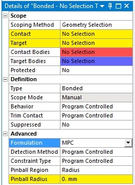
One way to get a good understanding of what bonded contact is doing is to set the Formulation to MPC.
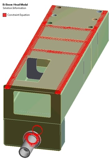
When you do this, after you solve, click on the Solution Information folder and the main window switches from Graphics to Worksheet. Click the tab on the main window back to Graphics and you will see a plot of the Constraint Equations (CE) that make up an MPC Bonded Contact. You can see and example of them in the image below where the flat side of a sheet metal box is bonded onto the U shaped part and some internal stiffeners.
Another important feature is Pinball Radius. On your test model, make the large flat plate have smaller elements, instead of 5 element across the width, make it 25 elements. I don't know the width of that plate, but say it is 100 mm, so each element would be 4 mm wide. Now try setting the Pinball radius to 5 mm and solve. Then set it to 10 mm and solve. Then set it to 25 mm and solve. Look at how the red CE elements reach further out across the plate. Please try this out and reply with some images. Thanks.
Note that if you set the Pinball radius to <1 mm, the solution may fail because no nodes on the plate will be close enough to form a CE.
2) There will be some difference between sharing nodes along an intersection line and using bonded contact. Large increases in stiffness is not a big problem with Bonded Contact, it is a big problem when a Remote Displacement or Joint is used with the Behavior set to Rigid and the scope is a large face.
3) Bonded contact can be used in Large Deflection nonlinear analysis where large angles of rotation are present. Bonded contact should be avoided if material plasticity is present in the area of the bonded contact. The help explains that you can have a Linear Model, which solves fast, and also use Bonded Contact. That is not true if you use Frictional Contact.
Regards,
Peter -
March 28, 2020 at 10:00 am
Jakub Drozdowski
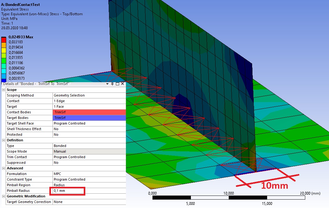
SubscriberHello. Thank you for comprehensive answer. I made the test that you described. If i understand well red lines represent constraint equation which are connecting nodes that are inside pinball radius region? But they are NOT rigid body elements, right ?
I made some tries with different pinball radius but nothing changing. Why is that ? Please look at the picture below there is no difference between 0,1mm radius and 50mm radius.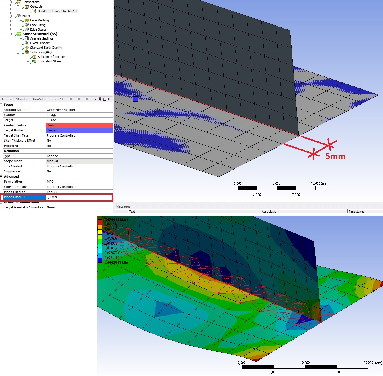
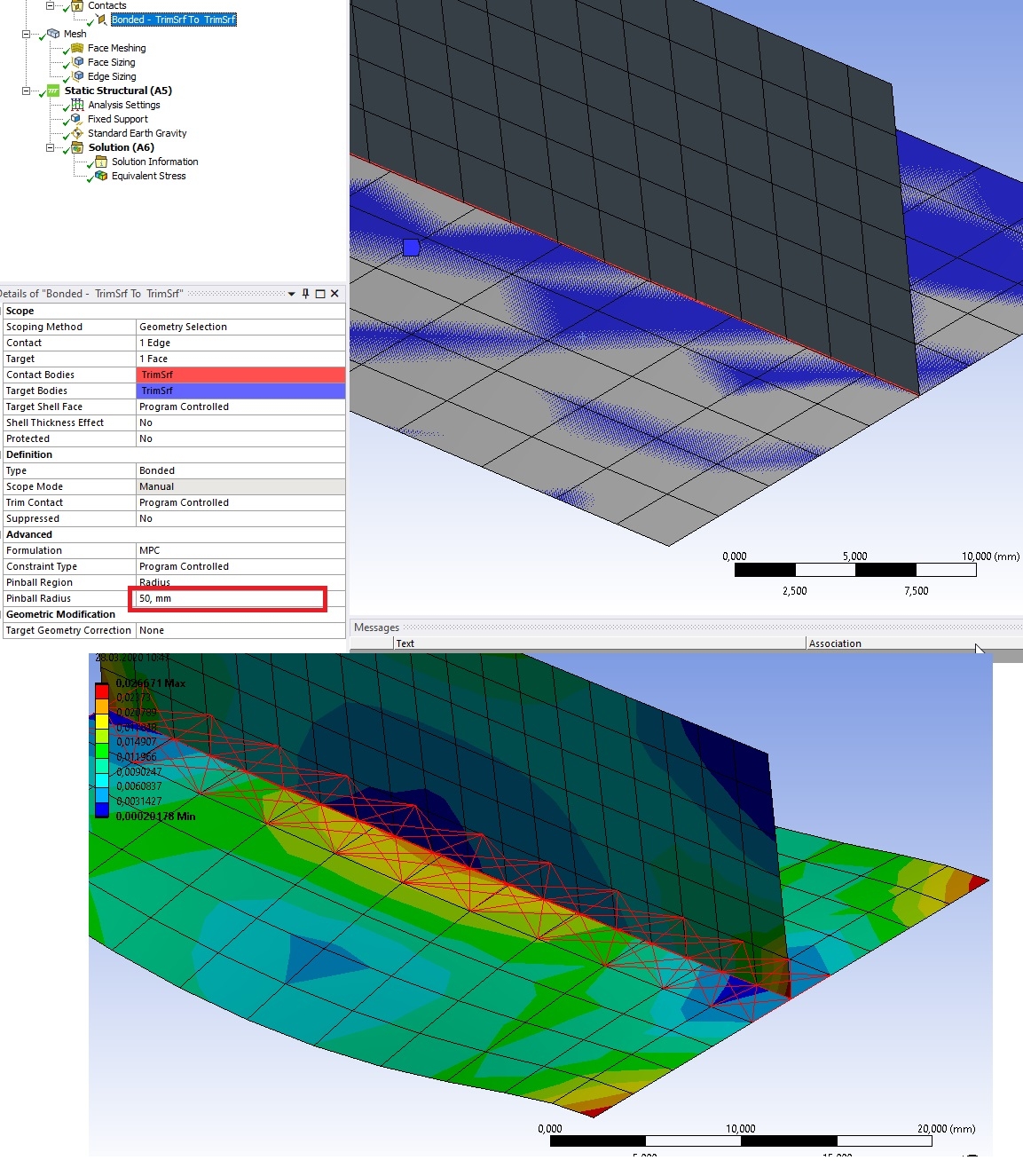
The red lines are only visible with MPC formulation. And what about other formulation ? What they are doing with nodes ? If I leave formulation as Program controlled there is no red lines so I assume that MPC formulation is not the default one. -
March 28, 2020 at 1:19 pm
peteroznewman
SubscriberHello jdrozdowski,
Thank you for doing the test! I described what I expected to happen, based on descriptions in the ANSYS Help system like this...
so it is interesting that it did not work the way I expected.
From your test, my new understanding is that there must be an algorithm that decides when a node has "enough" connections and stops. I don't know for sure.
One part of the test, which is not important to do as it only can cause a problem, was to set the Pinball radius small, which you did, but that only works if there are an odd number of elements (like 11) across the width, which leaves no nodes at the centerline and makes a gap between the nodes on the vertical and nodes on the horizontal. You have 10 elements across the width, which create nodes along the centerline and no gap.
These MPC Constraint Equations are described in Chapter 15.14 of the Theory Manual of the Help system, which I don't find that helpful. MPC stands for Multi Point Constraint. This creates a set of equations, using Lagrange Multipliers, to enforce a set of requirements on the kinematics of the set of nodes on either side of a contact. MPC is similar to RBE3 elements that distribute a force to a set of nodes without adding any stiffness. This is in stark contrast to the CERIG elements that define a rigid region which is used in a Remote Displacement or a Joint when the Behavior is set to Rigid. This does add stiffness to the model (NASTRAN calls it an RBE2 element). Remote Displacements and Joints can also have the Behavior set to Deformable, then it uses RBE3 elements that don't add stiffness.
The default Formulation for Bonded Contact is Augmented Lagrange according to the Help system. The reason I like MPC is because I can do a visual check of where the contact may be missing in some areas and I can increase my pinball region to cause it to connect.
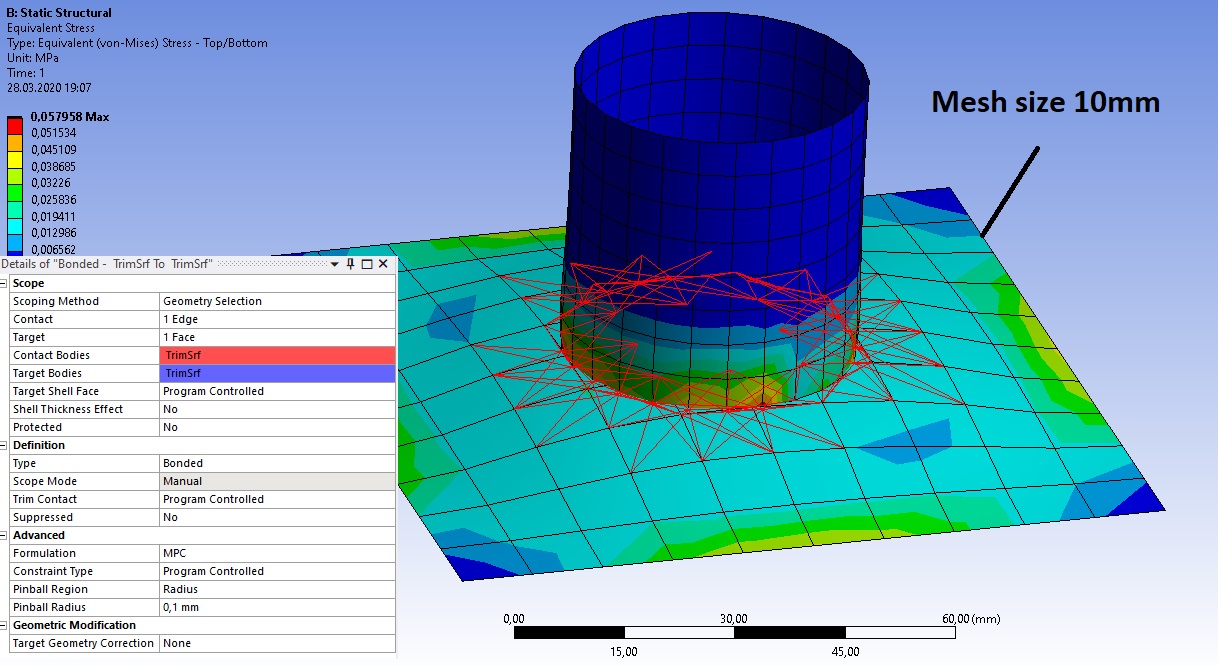
Here is another test you can try if you want. Make a cylindrical sheet body at the center of a flat square plate. This will create conditions where there is a large variation on the distance between nodes on the contact side and nodes on the target side of the contact. Play around with element size on each body. Flip the Target-Contact side of the contact by a right click on the contact. Try a number of different Pinball Radius values to see if you can get an intermittent bond around the circle.
-
March 28, 2020 at 6:16 pm
-
March 28, 2020 at 6:30 pm
peteroznewman
SubscriberGreat, thanks for the test results. I don't know why the Pinball radius is being ignored.
If in the cylinder on plate model, you go back to SpaceClaim and on the Workbench tab, click the Share Button, the circle will imprint on the plate, then you can go back to Mechancial, delete the contact and see the benefits of Shared Topology, which I prefer over Bonded Contact.
For others reading, here is another good discussion about this topic.
-
May 27, 2020 at 3:14 pm
AbelBerhanemeskel
SubscriberHi peteroznewman,
Can you please explain why bonded contacts are not desired when plasticity is present in the bonded region?
Thanks.
-
May 27, 2020 at 4:23 pm
peteroznewman
SubscriberBecause bonded contact uses equations to connect nodes together, but those equations don't know about the plasticity material model.
The elements that have the plasticity material model must be free to follow that model without extra equations hampering them.
-
May 27, 2020 at 5:01 pm
AbelBerhanemeskel
SubscriberThanks peteroznewman for replying to two of my posts quickly. I will go back to using shared topology. Do you have any tips on how to get pure hex mesh with shared topology? Because I been having problem getting multi zone to mesh. -
June 6, 2020 at 8:40 pm
Andreyteston
Subscriber -
March 20, 2023 at 4:45 pm
Venkata Prasada Rao Thalla
SubscriberThe Fixed joint is all 6 degrees of freedom are fixed, all three translations and three rotations.
Contacts are different category, in that contact is between two different types of regions with different properties.
Bonded contact is to just to transmit loading/displacments from one side to another side of joint, such that loads/displacments are transmitted through, specially without any node sharing or meshing at the joint. Bonding allows us to have different mesh types/mesh quality on eighter side of the joint.
-
- You must be logged in to reply to this topic.


Boost Ansys Fluent Simulations with AWS
Computational Fluid Dynamics (CFD) helps engineers design products in which the flow of fluid components is a significant challenge. These different use cases often require large complex models to solve on a traditional workstation. Click here to join this event to learn how to leverage Ansys Fluids on the cloud, thanks to Ansys Gateway powered by AWS.

Earth Rescue – An Ansys Online Series
The climate crisis is here. But so is the human ingenuity to fight it. Earth Rescue reveals what visionary companies are doing today to engineer radical new ideas in the fight against climate change. Click here to watch the first episode.
Ansys Blog
Subscribe to the Ansys Blog to get great new content about the power of simulation delivered right to your email on a weekly basis. With content from Ansys experts, partners and customers you will learn about product development advances, thought leadership and trends and tips to better use Ansys tools. Sign up here.

- Solver Pivot Warning in Beam Element Model
- Saving & sharing of Working project files in .wbpz format
- Understanding Force Convergence Solution Output
- User manual
- An Unknown error occurred during solution. Check the Solver Output…..
- What is the difference between bonded contact region and fixed joint
- The solver engine was unable to converge on a solution for the nonlinear problem as constrained.
- whether have the difference between using contact and target bodies
- Colors and Mesh Display
- Defining rigid body and contact

-
7272
-
4248
-
2899
-
1374
-
1322

© 2025 Copyright ANSYS, Inc. All rights reserved.

