-
-
September 11, 2018 at 11:21 pm
jonsys
SubscriberAs far as I have seen, the Force Convergence Worksheet helps a lot of experienced users, but I want to know exactly how. Like, for what information are you interested in? and how is that helpful?
Moreover, I wanted to clarify the following questions:
- Is Force Convergence "curve", the force generated by the iterations of FEM code?
- Does Force Criterion represent the input force defined by the user?
- What does "Time" on y-axis of the 2nd graph represent ?
Regards,
-
September 12, 2018 at 1:08 am
Sandeep Medikonda
Ansys EmployeeHi Jon,
Please see this section of the manual on how the newton-raphson method works.
This will give you some idea into how to read the force convergence plot. You are looking at how your solution/force is converging here by changing the solver output. Note that when the Magenta color i.e., the {F}-[KU] is below the teal color {R} you would see a sub-step convergence and the solution proceeds.
There is a very interesting article on a blog of our channel partners (PADT Inc) that talk about this in detail. Please look for it:
Overcoming Convergence Difficulties in ANSYS
The time in the second plot refers to your simulation time and the force criteria is a fraction of your reaction force (it can also be controlled from workbench)
Regards,
Sandeep
-
September 12, 2018 at 7:58 am
jonsys
SubscriberSandeep,
thank you for the suggestion, that was really helpful.
- Magneta color {F}-[KU]; {F} is Fa or Fnr?
- So teal color is {R}={Fa}-{Fnr}?- doesn't this mean that at the final converged solution, {R} should be close to 0?
- In what cases does Bisection Occure
Regards,
-
September 12, 2018 at 11:32 am
peteroznewman
SubscriberHi Jonsys,
I learned something new from Sandeep above.
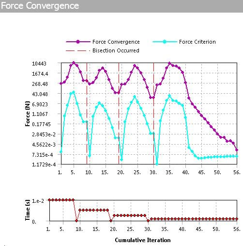
Below is a plot that shows you three bisections followed by an almost converged set of iterations, then the solver stopped.
You can see that the initial number of substeps was 100 (Time of 1e-2). Three bisections is 2x2x2 or a factor of 8 and that was not enough. I would use a factor of 10 and set the Initial Substeps to 1000 on the next try.
One case when a Bisection occurs is when it has used up the maximum number of iterations, which by default is set to 26. This is generally a good number, but when you see an almost converged condition, like the last part of the graph above, you want the solver to keep iterating, since it's almost there! There is a command snippet that can override the default number of 26, and that is
NEQIT,50
where you can type in larger numbers than even 50, like 100. I use this a lot. The only time it is wasteful is when it's never going to converge, it keeps the solver running on a futile task.
I sometimes watch the N-R Residual graph plot new points as it solves and if I see it diverging for many points instead of converging, I will interrupt the solution and perhaps change to a smaller time step (larger number for Initial Substeps), and then restart the solution. That way I don't have to wait for 26 iterations for a bisection to occur. That is helpful on large models that might take tens of minutes per iteration.
In the plot above, step 1 needed the substeps to converge, but step 2 has a Minimum Substeps that is larger than required. I often set Minimum Substeps to a large number to get a smooth curve of the history from step 1 to step 2, but if all you were interested in was the result at step 2, the plot shows you to try a larger Initial and larger Minimum number of substeps in step 2 to get to the final result.
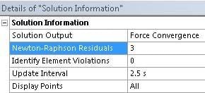
You must set the number of Newton-Raphson Residuals to a number larger than the default of 0, so that when the solver fails to converge, you can see which elements were having difficult converging and take some corrective action, like using smaller elements or softening the contact stiffness. Here is an example.
I also have a post with a video example.
Regards,
Peter
-
September 12, 2018 at 1:12 pm
Sandeep Medikonda
Ansys EmployeeHi Jon,
Yes, the {F} in {F}-[KU] represents the applied force {Fa}.
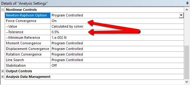
Also, you are right in your second point. In an ideal situation, we want the residuals to be zero, but this is very hard to achieve especially for non-linear problems. Hence, we set a limit on how much is acceptable, so 0.5% of the applied force (by default) is good enough assumption for most problems but you can change this using the settings I show above.
Peter already provided an excellent answer to your question on bisection. So, in short, if the solution doesn't converge in a specified number of iterations the solver will try to bisect or divide the load/time in half and then try to achieve converge in that particular sub-step.
Regards,
Sandeep -
September 12, 2018 at 7:26 pm
jonsys
SubscriberPeter,
Sandeep,
thank you very much for the clear explanation together with the sections and videos that you suggested.
There are a couple other posts in which I got helpful information from you but I can not mark only one comment as the answer since there are multiple valuable comments. On the other side, I want posts that have answers, to be marked like that for the future users of the forum. Anyway, the question is answered.
Regards,
Jon -
September 25, 2018 at 2:37 pm
jackhero
Subscriber@ Peter,
With reference to your post here with in this thread, as I quote below,
You can see that the initial number of substeps was 100 (Time of 1e-2). Three bisections is 2x2x2 or a factor of 8 and that was not enough. I would use a factor of 10 and set the Initial Substeps to 1000 on the next try.
Initial number of substeps I assume were set in the Analysis settings by ourselves so it is a known parameter. I can see the bisection in your attached force-convergence graphs, I would like to to ask how did you do the three bisections 2x2x2 ?
-
September 27, 2018 at 3:53 am
peteroznewman
SubscriberOne bisection cuts the step size in half, so you need twice the number of substeps to avoid that next time. If that happens three times in a row, it is 2x2x2 on the number of substeps needed next time.
-
October 5, 2018 at 1:14 pm
akhemka
Forum ModeratorSimilarly, when convergence happens the next iteration jump will be based on the minimum substep size indicated.
Regards,
Ashish Khemka
-
February 19, 2020 at 12:59 am
danilouen22
SubscriberHello there, I tried using what you said here in my own simulation and it doesn't converge even with the NEQIT, 100 command, I also used the newton-raphson residuals to try and locate where the error is coming from but I haven't been able to get anywhere. I posted it on a new discussion, could you help me out with it? the name of the discussion is
How to create proper boundaries/constraints to avoid "internal solution magnitude limit..." error.
-
August 18, 2020 at 6:01 am
Pramod_cae
SubscriberArray nhello,nonce you find NR force location from solution you can optimize that particular contact location.nchange detection method- nodal-normal to target nnormal stiffness -factor to 0.2 (default value is 1) n
-
- You must be logged in to reply to this topic.


Boost Ansys Fluent Simulations with AWS
Computational Fluid Dynamics (CFD) helps engineers design products in which the flow of fluid components is a significant challenge. These different use cases often require large complex models to solve on a traditional workstation. Click here to join this event to learn how to leverage Ansys Fluids on the cloud, thanks to Ansys Gateway powered by AWS.

Earth Rescue – An Ansys Online Series
The climate crisis is here. But so is the human ingenuity to fight it. Earth Rescue reveals what visionary companies are doing today to engineer radical new ideas in the fight against climate change. Click here to watch the first episode.

Ansys Blog
Subscribe to the Ansys Blog to get great new content about the power of simulation delivered right to your email on a weekly basis. With content from Ansys experts, partners and customers you will learn about product development advances, thought leadership and trends and tips to better use Ansys tools. Sign up here.

- Solver Pivot Warning in Beam Element Model
- Saving & sharing of Working project files in .wbpz format
- Understanding Force Convergence Solution Output
- User manual
- An Unknown error occurred during solution. Check the Solver Output…..
- What is the difference between bonded contact region and fixed joint
- The solver engine was unable to converge on a solution for the nonlinear problem as constrained.
- whether have the difference between using contact and target bodies
- Colors and Mesh Display
- Defining rigid body and contact

-
7272
-
4248
-
2899
-
1374
-
1322

© 2025 Copyright ANSYS, Inc. All rights reserved.


