-
-
March 12, 2018 at 5:15 pm
vaibhav jain
Subscriberhi, i am getting the values of deformation in explicit but it is showing 0 value of principle stress. what to do?
-
March 12, 2018 at 6:03 pm
peteroznewman
SubscriberArchive your model and attach the .wbpz file to your post above so we can look at it.
The file size limit to attach is 120 MB so if your file is larger than that, select Mesh in Mechanical (or Model in Workbench) and Clear Generated Data, then save your model and File, Archive... again. This will be a smaller file because it won't have a mesh included.
Please post a description of what you are trying to accomplish with the simulation.
-
March 12, 2018 at 7:54 pm
vaibhav jain
Subscriber -
March 13, 2018 at 5:52 pm
peteroznewman
SubscriberYou marked your post above as "Is Solution" so are you saying your don't need any help? Unmark that and save that check for when your issue is resolved.
I took a look at your geometry. You have the front tube buried inside the plate, which is a serious problem to fix before you run the analysis. I changed the plate extrusion thickness to 7.3 mm to get the plate to just about touch the tube. You had an extrusion thickness of 30 mm.
I also made the plate rigid instead of flexible, so it doesn't matter that it is now thin. I also deleted the contact between the tube and plate. It is not needed. Does you model run better with these changes?
-
March 18, 2018 at 10:40 am
vaibhav jain
Subscriberfirst of all thanks peteroznewman for the solution, my problem is not solved yet. i ticked it by mistake.
can you please tell me the calculation involved in explicit and also the effect of wall and its thickness and distance between wall and rollcage used in calculation as you haven taken the thickness as 7.3 mm.
i have done front impact static structural analysis. i have applied 8000 newton force front and fixed suspension points. now i have to do the same analysis in explicit dynamics. what should be the velocity, end time and other boundary conditions necessary to perform the explicit analysis. is distance between wall and rollcage have some effect. roll cage material is aisi 4130, yield strength is 460 mpa, thickness of pipe is 1.67 mm, weight of roll cage 25 kg.
please give me the calculation as i don't know how to get the same boundary condition in explicit as it was in static strucutral. i will do the analysis by myself.
-
March 18, 2018 at 1:15 pm
peteroznewman
SubscriberIn your post from 5 days ago, you said velocity 10000 m/s. That is 36000 km/hr or Mach 29. You must have made a mistake, since that is at least 100 times faster than any car I have been in. What impact velocity do you want to study? You could study more than one. You could look at 50 km/hr and 100 km/hr, it's up to you to choose. The velocity of the car and the presence of the fixed wall are the only boundary conditions you need.
The initial distance between the cage and the wall should always be zero for Explicit Dynamics. The results are the same if you include a gap between the cage and the wall, the only difference will be a longer wait for the solution, since the solver will spend time moving the cage toward the wall.
Why did you choose 8000 N front force in the Static Structural analysis? What assumptions went into choosing that number? What is the total mass of the car?
Explicit Dynamics analysis is performed to get different types of results from Static Structural analysis. In Static Structural, you can ignore the mass of the parts if gravity is not a significant force in the problem. Explicit Dynamics is solving F = ma so you must include all the mass in the problem. What is the engine mass? Let's assume it is 100 kg. While you are interested in the cage, you can't leave out the 100 kg mass that is attached to it. The engine connects to the cage at four points. In the model, you can add a point mass at the coordinates of the center of the engine, and connect that point to the four points on the cage. Then when the front hits the wall, the engine mass will pull on the cage as it decelerates. What is the mass of a front wheel and suspension components? Let's assume 20 kg. You have to add a point mass at the center of mass of each wheel and connect each mass to the frame at the suspension connection points.
Once you have all the mass attached to the cage, you can run the simulation at your chosen initial velocity. The most interesting result will be the reaction force at the fixed wall. This will build up to some maximum over time and then reduce as the energy and velocity are dissipated. Your end time has to be long enough so you have seen the maximum wall reaction force and the force is clearly diminishing. At a low enough initial velocity, the cage will elastically bounce off the wall with no damage.
-
March 18, 2018 at 3:45 pm
vaibhav jain
SubscriberThe weight of the car is 200 kg along the driver. I have taken 4g acceleration to test the vehicle. the velocity of the vehicle is 50 km per hour. I have queries regarding the end time whether it would be 1 milli second or less than that. How to calculate it.
it is an electric vehicle and i have attached the weight of battery and suspension and performed the analysis but it is showing very less stress values. -
March 18, 2018 at 4:12 pm
vaibhav jain
Subscriberwill you please attach the analysis file if it possible. the video you posted is showing motion of vehicle continuously but in my case the vehicle moves in one particular moment and then it remains stationary for the rest of animation.
-
March 18, 2018 at 4:28 pm
peteroznewman
SubscriberRegarding your question on End Time. Please reread the paragraph I wrote above, which I copy below...
The most interesting result will be the reaction force at the fixed wall. This will build up to some maximum over time and then reduce as the energy and velocity are dissipated. Your end time has to be long enough so you have seen the maximum wall reaction force and the force is clearly diminishing.
I am currently running a simulation where I put in 144 kg in the back of the cage and adjusted the density of steel so the total weight is 200 kg. I used an initial velocity of 50 km per hour (13.9 m/s). I ran it for 1 ms and plotted the velocity of the engine, which was -13.8 m/s (50 km/h) at t=0. After 3 ms is was still -9 m/s so I will have to continue to add more time to the simulation until the velocity reaches 0 m/s, which is the point at which the 144 kg mass in the back will start its rebound and pick up a positive velocity. You can continue an analysis without losing the computation done from t=0. Each millisecond of simulation time takes my computer about 10 minutes to solve on 14 cores.
I will post an archive and video when it finishes.
I am using ANSYS 19.0 on a full license which is the first version to allow point masses and joints to be included in the model. I see you have been running ANSYS 15. How do you attach the mass of the batteries to the cage?
The archive has a mesh that is too many elements to run on the Student license.
-
March 18, 2018 at 5:16 pm
vaibhav jain
Subscriberi will open in my college. i am facing lots of difficulties in explicit. please attach it after you have done.
-
March 18, 2018 at 9:05 pm
peteroznewman
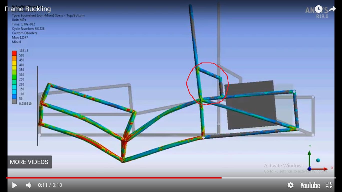
SubscriberThe simulation ran to 26 ms, but then the connection of the 144 kg battery box in the rear became numerically unstable. A better connection to the box or a point mass may be a better choice for the next model.
https://youtu.be/y12LcGh1noI
The impact force with the wall was around 300,000 N until the bucking became substantial.
The velocity of the 144 kg mass did not reach zero before the numerical instability occurred at the end.
The attached archive is from ANSYS 19.0 but the mesh is too large for the Student license.
-
March 19, 2018 at 12:46 pm
vaibhav jain
Subscriberhi, i have ansys 18. if it is possible to convert it in ansys 18 please tell me or please attach ansys 18 file if possible.
-
March 19, 2018 at 1:12 pm
peteroznewman
SubscriberDo you mean 18.2 or 18.0? I have 18.2 or I have 17.2 but I can't use point masses or joints in those older versions. What is the mass of the battery pack and how does it connect to the cage? Can you send geometry that shows that?
-
March 19, 2018 at 4:32 pm
-
March 19, 2018 at 9:39 pm
vaibhav jain
Subscriberin my animation rollcage is moving at once and in your video rollcage is moving every point of time. please look what are the mistakes that i have done.
-
March 19, 2018 at 10:06 pm
peteroznewman
SubscriberMy animation is smooth because I requested 500 frames in the Output section of the Analysis Settings. The default is 20 frames. I also requested 500 frames of Contact Force and that was over 50 ms End time, so when I stopped the simulation at 25 ms, I had 250 frames.
Are you going to upload a file for me to look at?
In the animation above, the 144 kg block in the back is tied to four frame points around the bottom tubes.
In the animation below, I have a 144 kg point mass at the center of the block, but I tied it to the top horizontal tubes at the bottom of your red circle, much like where your battery is attached, but my CoM is lower.
https://youtu.be/0KppxvUf-lA
-
March 20, 2018 at 8:32 pm
vaibhav jain
Subscriberhello, i has made the wall rigid but rollcage is penetrating the wall. how to solve it. in my rollcage stress is mainly in the front portion of rollcage but in yours entire rollcage gets deformed
-
March 20, 2018 at 8:52 pm
vaibhav jain
Subscriberhere is the file
-
March 20, 2018 at 9:45 pm
peteroznewman
SubscriberI don't see an attached file. The file size limit is 120 MB. If your .wbpz file archive is larger, you can Clear Generated Data on the mesh, Save As a new file name, then File Archive to save a smaller file.
-
March 22, 2018 at 2:34 am
peteroznewman
SubscriberVideo #1 shows the edits to your model to get it to run like my model. There is another video coming.
https://youtu.be/E2vC0heJmhs
-
March 22, 2018 at 2:37 am
peteroznewman
SubscriberVideo #2 completes the editing. The model is running, then I will attach the ANSYS 17.2 archive that you can run in ANSYS 18.0
https://youtu.be/iYtdnVcjif8
-
March 22, 2018 at 3:29 am
peteroznewman
SubscriberHere is the result of 40 minutes computation for 20 ms of time on a 2 core computer. ANSYS 17.2 archive that you can run in ANSYS 18.0
https://youtu.be/cIW_gr2-XUU
-
March 22, 2018 at 2:56 pm
vaibhav jain
Subscriberhi, first of all thanks for your time. how to correlate explicit results with static results. as in static i have applied 4g force (8000 N). i have taken time of impact .35 second and velocity 14 m/s. i want to compare the static and explicit results to get the error. and one more thing is how to interpret the solution summary to know that the results are correct or there is minimum error.
-
March 22, 2018 at 4:52 pm
peteroznewman
SubscriberYou can show your appreciation by clicking "Like" on the posts that are helpful.
I forgot one thing in the videos, instead of a fixed support to the wall, I created a translational joint, and applied a joint load of 0 displacement. That way, I could plot the reaction force on that joint. That trick only works in Release 19.0 as joint are not supported in earlier releases. I didn't see how to plot reaction force without that trick.
I solved the model out to 100 ms on my 12 core computer. It took 45 minutes to compute. Looks like you need to add wheels and a ground plane to this model.
One of the ways to check if the solution has acceptable error is to look at Energy Conservation, which shows Energy Error.
The solver will stop if the Energy Error exceeds the threshold you set.
You may see this error when that happens:
Problem terminated .... energy error too large
-
March 22, 2018 at 10:23 pm
peteroznewman
SubscriberI reran the model in ANSYS 19.0 for 2 hours. I also added a joint that constrained the intersection of three tubes on the bottom level near the front to have Y=0 to act somewhat like "wheels" to stop the frame from buckling downward the way it does in the previous videos.
https://youtu.be/xSjXbVKIdp4
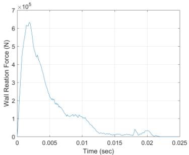
Here is the plot of the wall reaction force (N). It has a peak above 600,000 N and looks like the impact lasts about 20 ms.
-
March 23, 2018 at 2:55 am
peteroznewman
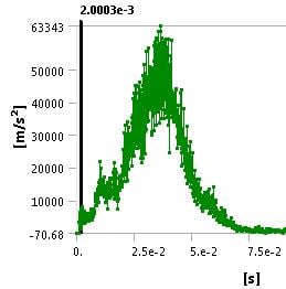
SubscriberIn my last model, I plotted the acceleration of the short vertical tube near the battery cage.
I could smooth this plot, but an estimate of the peak acceleration is 50,000 m/s^2 or 5,000 g.
In your Static Structural model, you used a force of 8,000 N on a 200 kg car, which would produce about a 4 g acceleration. Why do you think 4 g is a good number given the 5,000 g result I show in the Explicit model?
-
March 23, 2018 at 9:13 am
vaibhav jain
Subscriberthe maximum acceleration the human body can bear is 7g and in normal condition too the impact is not greater than 7g.
-
March 23, 2018 at 10:50 am
peteroznewman
SubscriberThanks, now I understand. What you are saying is that this is a design specification. A steel frame with a rigid shape made of straight tubes gives a very high deceleration. Cars are designed with crumple zones in order to reduce the deceleration. Changing the front tubes from straight to curved would reduce the peak deceleration, but that would also crush the driver's legs. Do you plan to add a crumple zone structure to your model to reduce the acceleration at the driver's seat below 7g? If so, you can start a new discussion.
-
March 11, 2019 at 10:03 pm
peteroznewman
Subscribertungfw,
This is an old discussion which someone else started.
Please copy and paste into a New Discussion, then delete your post above.
When you start a new discussion, you will be notified of replies and can close the discussion when you get a solution to your problem.
-
March 18, 2019 at 8:50 am
tungfw
SubscriberI have a kinda similar issue about the joint, Peter can you see my new discussion?
https://dev7.webdevonline.net/AIS/ais-multisite/forum/forums/topic/linking-the-relationship-between-a-body-with-another/
-
April 13, 2019 at 4:31 am
indjra
Subscribercan you tell me, how to setting the time sampling in x axis on your graphic?
-
April 13, 2019 at 2:57 pm
-
- You must be logged in to reply to this topic.


Boost Ansys Fluent Simulations with AWS
Computational Fluid Dynamics (CFD) helps engineers design products in which the flow of fluid components is a significant challenge. These different use cases often require large complex models to solve on a traditional workstation. Click here to join this event to learn how to leverage Ansys Fluids on the cloud, thanks to Ansys Gateway powered by AWS.

Earth Rescue – An Ansys Online Series
The climate crisis is here. But so is the human ingenuity to fight it. Earth Rescue reveals what visionary companies are doing today to engineer radical new ideas in the fight against climate change. Click here to watch the first episode.

Ansys Blog
Subscribe to the Ansys Blog to get great new content about the power of simulation delivered right to your email on a weekly basis. With content from Ansys experts, partners and customers you will learn about product development advances, thought leadership and trends and tips to better use Ansys tools. Sign up here.

- Explicit dynamics ERRORS
- explicit dynamics
- turning simulation
- getting zero maximum and minimum stress value in explicit analysis
- How to figure out impact force in Explicit Dynamic Analysis
- How do get Full values instead of just minimum and maximum ?
- Running an explicit dynamics simulation on a composite plate
- Monte Carlo Simulation
- Euler Domain Restricting Simulation
- How to solve Energy error too large

-
7272
-
4248
-
2899
-
1374
-
1322

© 2025 Copyright ANSYS, Inc. All rights reserved.


