-
-
April 10, 2018 at 6:27 pm
hugo CFD
SubscriberHello.
I have some doubts that i would like to clarify. Consider a fixed plate heat exchanger air-air with quasi counter flow. The heat exchange is through forced convection.
How should I calculate the coefficient of heat transfer? Directly from the fluent across the surfaces integrals --> area weighted average or through the formula h = q / at, where do I take the values of twall and tref and q from the fluent?
The next question is about boundary conditions. when defining the boundary conditions, is it necessary to consider heat transfer by convection between the air and the plate, by selecting the CONVECTION point in the THERMAL conditions?
Thanks
-
April 14, 2018 at 3:23 pm
Raef.Kobeissi
SubscriberHello Hugo,
Question 2 first: It depends on how you're simulating your case, if it is forced convection I would assume air flow is involved around the fixed plate HE and in this case you don't need to use convection.
Question1: I am assuming that you are using a solid wall(meshed) to simulate the HE, in that case you can calculate it through fluent as you mentioned. Can you attach the case file and I can show you how to do it through a small video or series of pictures.
Regards
-
April 19, 2018 at 8:48 am
hugo CFD
SubscriberHello
I am sending the study case. I have read that in certain situations, a UDF is required to calculate h. Am i correct? What are these situations?
Regards
-
April 26, 2018 at 1:56 pm
raul.raghav
SubscriberFor laminar flow in Ansys Fluent, the convective heat transfer coefficient (h) is calculated based on the equation:
h = q / (T_wall - T_ref); where T_ref is the reference temperature you provide. You need to be careful providing the T_ref value, as that can result in the underestimation or overestimation of convective heat transfer coefficient (h) value. I'd highly recommend you to go through the following paper which compares the convective heat transfer coefficient obtained with T_ref value evaluated in different ways:
Determination of surface convective heat transfer coefficients by CFD
You can plot contours of the local heat transfer coefficients. And you can use "Surface integrals" to plot the average heat transfer coefficient (see image below):
PS: I haven't checked any of the inputs or outputs in your case file, so I won't be commenting on the results.
-
April 29, 2018 at 10:31 am
Raef.Kobeissi
SubscriberHi Hugo, have you been able to resolve your issue?
-
May 3, 2018 at 11:26 am
hugo CFD
SubscriberNo. I am looking for another way to get heat transfer coefficient, instead to calculate by T ref method.
Hugo
-
May 3, 2018 at 1:53 pm
raul.raghav
SubscriberHugo, as far as I'm aware of, heat transfer coefficient can either be calculated using the standard definition as I mentioned my previous post or by the Reynolds Analogy as turbulent heat transfer is modeled using the analogy.
From the Reynolds analogy: h = (Cf/2) * density * U_ref * Cp
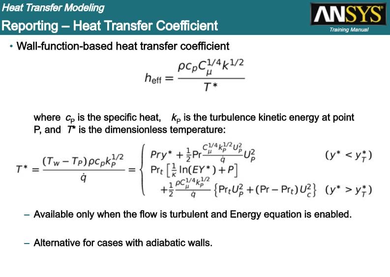
where Cf is the skin friction coefficient, and U_ref is the reference velocity, which is difficult to be estimated. For turbulent flows, you can use wall functions to evaluate h:
-
May 3, 2018 at 11:14 pm
hugo CFD
Subscriberyes. you are right. maybe i didn´t express well.
i considered follow expression to calculte heat transfer coefficient: h = q / ( T _ wall - T _ adj)
q is heat flux and I get this value from fluent (surface integrals---wall flux--- total surface heat flux) referring to the boundary condition "heat transfer 1".
T_wall is a temperature of the wall and i get this value from fluent referring to the boundary condition ""heat transfer 1-shadow".
T_adj is the temperature of the first fluid layer following the wall referring to the boundary condition "heat transfer 1".
My problem is how i get the values of the expression from fluent. I don t know if what i have considered is right.
Hugo
-
May 4, 2018 at 12:48 am
raul.raghav
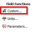
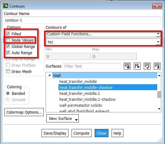
SubscriberYou can define a custom field function with the formula shown in the image below [Total Surface Heat Flux / (Wall Temperature - Static Temperature)]. Once you've created the function, use a contour plot to display the function. Make sure when you create the contour plot, you have the "Node Values" unchecked.
-
May 4, 2018 at 4:59 pm
-
May 5, 2018 at 5:41 pm
raul.raghav
SubscriberThe heat transfer coefficient that is area-weighted average is the average heat transfer coefficient. The contour plot shows the local heat transfer coefficient. And the heat transfer coefficient depends on the fluid, hydrodynamic and thermal conditions and also on the geometry under consideration.
I'm not sure why the coefficient is negative though. Again as I mentioned in my earlier posts, the way you calculate the coefficient makes a whole lot of difference.
-
May 22, 2018 at 8:58 am
hugo CFD
SubscriberHi.
How can I obtain/calculate the local heat transfer coefficient along the length of the heat exchanger? And make a chart of this behavior?
hugo
-
May 22, 2018 at 2:55 pm
-
February 10, 2020 at 8:59 am
atulsingh92
Subscriber@Raul.raghav Could you please explain in more detail, as to how, can one define this reference temperature? The thing is, this value, is good enough to make the nusselt number negative.
So, lets say I am simulating for internal flow in a corrugated tube with periodic bc. (yes i have segregated solver and const heat flux bc as mentioned in Ansys manual). The reference temperature I have chosen, is by reverse calculating the nusselt number mentioned in an experimental paper. i.e the paper mentiones the fluid -water entering at 26 degrees C and then showed a nusselt of 65 for example. The q applied is 21100.
This would leave me by htc= 21100 / (26 - x); Nu = 60 = htc * 0.00575 / 0.61; I enter this x as my reference temperature.
But the question is , here, I knew my nusselt from an experimental data, what to give when I dont know this before hand
Also, the way I mentioned, is it the correct way? -
July 7, 2022 at 2:06 pm
irineupetri
SubscriberHi.
Follow the advice from colleagues above, but don't forget to consider the outer walls of your adiabatic system, setting the heat flux equal to zero (Q = 0) on the external walls.
Good luck
-
December 22, 2022 at 6:39 pm
Mughees Shahid
Subscriberhow we can use convection heat transfer coefficient value in cfd ansys workbench 19 need guidance Thank you
-
March 8, 2023 at 11:54 am
Maisha Nusrat
SubscriberHello I have been facing a problem regarding heat transfer coefficient. I installed 2023 R1 version yesterday. Then I run the simulation using water and a nanofluid. After the simulation is over, I tried to determine area average of surface of heat transfer coefficient on wall. But it keeps showing me error repeatedly and isnt giving me any sort of value. But all these days I was using an older version of ansys where none of these errors were shown.
I really need help right now. Even in data qualities, I have chosen surface heat transfer coefficient saveral times but in the results, it is not showing this parameter.
Can someone help?
Is there other way to determine the coefficient?
-
- You must be logged in to reply to this topic.


Boost Ansys Fluent Simulations with AWS
Computational Fluid Dynamics (CFD) helps engineers design products in which the flow of fluid components is a significant challenge. These different use cases often require large complex models to solve on a traditional workstation. Click here to join this event to learn how to leverage Ansys Fluids on the cloud, thanks to Ansys Gateway powered by AWS.

Earth Rescue – An Ansys Online Series
The climate crisis is here. But so is the human ingenuity to fight it. Earth Rescue reveals what visionary companies are doing today to engineer radical new ideas in the fight against climate change. Click here to watch the first episode.

Ansys Blog
Subscribe to the Ansys Blog to get great new content about the power of simulation delivered right to your email on a weekly basis. With content from Ansys experts, partners and customers you will learn about product development advances, thought leadership and trends and tips to better use Ansys tools. Sign up here.

- Floating point exception in Fluent
- What are the differences between CFX and Fluent?
- Heat transfer coefficient
- Difference between K-epsilon and K-omega Turbulence Model
- Getting graph and tabular data from result in workbench mechanical
- The solver failed with a non-zero exit code of : 2
- Suppress Fluent to open with GUI while performing in journal file
- Mesh Interfaces in ANSYS FLUENT
- Time Step Size and Courant Number
- error: Received signal SIGSEGV

-
7272
-
4248
-
2899
-
1374
-
1322

© 2025 Copyright ANSYS, Inc. All rights reserved.


