-
-
April 6, 2019 at 9:17 pm
JoshuaValdivia
SubscriberHello,
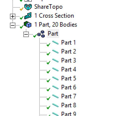
I am currently having issues when solving my car chassis beam element model. I uploaded the drawing from Solidworks. There are bent elements so I have made those pipes, and added pipe idealization while also switching element order to quadratic in mesh details.
I have fixed supports at vertices in the rear of the car and a load acting on a vertice in the front of the chassis. I then receive three solver pivot warnings. When I go to object and suppress it, another body just gives the same warning.
-
April 7, 2019 at 12:39 am
peteroznewman
SubscriberThe solver pivot warnings could be caused by bodies that are not connected. How do you know all the beam ends are connected to each other?
If you drop a Modal analysis on top of the Model cell of the analysis you are doing, and solve the Modal system, if you get any zero frequency modes, that tells you there are unconnected bodies. They will be the ones floating around in the Deformation plot of the Modal solution.
-
April 7, 2019 at 1:28 am
JoshuaValdivia
SubscriberThank you for replying. I have tried that and attached a picture to this post. I don't understand why less complicated structures are working.

This triangle/arc structure works fine, and I am 99% sure i set up everything the same way.
I also have solved a section of the chassis, but I do not understand why the arcs are connecting in the front. I am beginning to assume the reason the frame isn't solving is due not of the arcs connecting throughout the model
Is there any way you could explain to me what's going on?
Again, I appreciate the help. Thank you
-
April 7, 2019 at 1:44 am
peteroznewman
SubscriberIf you have used bonded contact to connect one vertex to another, there is the Contact Tool to check that contacts are closed, and you can adjust the pinball radius to make them change status from open to closed.
How were you trying to connect these end points?
-
April 7, 2019 at 3:09 am
-
April 7, 2019 at 3:22 am
sathya
SubscriberHi Eventhough you share topology ,make sure the gap between any two line body is less than cad tolerance.or you can zoom in and check distance between those vertices.if high you have to close the gap manually. -
April 7, 2019 at 10:36 pm
JoshuaValdivia
SubscriberI figured it out. Thanks for the help. The lines were only connected at nodes, not when one line met in the middle of another line. I added bonded contacts whenever this occurred.
-
August 26, 2023 at 9:06 am
Aniket Jadhav
SubscriberI am trying to solve the "Direct joining of 2D carbon/carbon composites to Ti–6Al–4V alloy with a rectangular wave interface J.T. Xiong a,b,∗, J.L. Li, F.S. Zhang, X. Lin a, W.D. Huang" but i am unable to get the resulthttps://drive.google.com/file/d/1WtMdCku9CF7FY9FtfxsN1vvH4fBxB1VI/view?usp=drive_link
-
- You must be logged in to reply to this topic.


Boost Ansys Fluent Simulations with AWS
Computational Fluid Dynamics (CFD) helps engineers design products in which the flow of fluid components is a significant challenge. These different use cases often require large complex models to solve on a traditional workstation. Click here to join this event to learn how to leverage Ansys Fluids on the cloud, thanks to Ansys Gateway powered by AWS.

Earth Rescue – An Ansys Online Series
The climate crisis is here. But so is the human ingenuity to fight it. Earth Rescue reveals what visionary companies are doing today to engineer radical new ideas in the fight against climate change. Click here to watch the first episode.

Ansys Blog
Subscribe to the Ansys Blog to get great new content about the power of simulation delivered right to your email on a weekly basis. With content from Ansys experts, partners and customers you will learn about product development advances, thought leadership and trends and tips to better use Ansys tools. Sign up here.

- Solver Pivot Warning in Beam Element Model
- Saving & sharing of Working project files in .wbpz format
- Understanding Force Convergence Solution Output
- User manual
- An Unknown error occurred during solution. Check the Solver Output…..
- What is the difference between bonded contact region and fixed joint
- The solver engine was unable to converge on a solution for the nonlinear problem as constrained.
- whether have the difference between using contact and target bodies
- Colors and Mesh Display
- Defining rigid body and contact

-
7272
-
4248
-
2899
-
1374
-
1322

© 2025 Copyright ANSYS, Inc. All rights reserved.


