TAGGED: ansys-student, ansys-workbench, convergence, structural
-
-
January 20, 2019 at 3:18 am
Beny386
SubscriberHello,
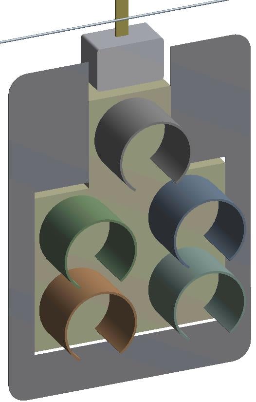
I've been working on a model of a cable supported traffic signal assembly on Ansys 17.2 and I'm trying to run a non-linear analysis. I've set up a modal, static structural, transient structural, and a response spectrum analysis. I first attempted to run the static structural analysis and I'm receiving a consistent error message shown below. I'm on a full version license without any limits.
Error Message: The solver engine was unable to converge on a solution for the nonlinear problem as constrained. Please see the Troubleshooting section of the Help System for more information.
I thought the error may have originated from the attachment points of the traffic signal hangers to each cable and attempted to refine the mesh to no use. I also attempted refining the mesh at the interface of each component of the traffic signal to no use either.
Please let me know of suggestions that could fix this error. Attached below is the file of my model.
Thank you
Beny
-
January 20, 2019 at 7:17 am
peteroznewman
SubscriberHello Beny,
Please save a Workbench Project Archive .wbpz file to attach to your post instead of the zip of the .wbpj file, which is useless on its own.
Regards,
Peter -
January 20, 2019 at 2:08 pm
-
January 21, 2019 at 3:50 am
Beny386
SubscriberHello Peter,
I attached the Project Archive.wbpz file for the model I've been working on for your viewing.
Thank you.
Beny
-
January 21, 2019 at 4:03 pm
peteroznewman
SubscriberHello Beny,
I opened your model, unfortunately, I can't open it in Release 17.2, so I opened it in 19.2. I duplicated the Static Structural analysis block to separate it from the Modal analysis. I meshed and ran the model. The solver issued some Warnings that need to be looked into:
*** WARNING *** CP = 161.227 TIME= 10:25:29
Node 44913 connects both contact element 1562556 and target element
1564048. Please check the model carefully.
*** WARNING *** CP = 161.227 TIME= 10:25:29
Node 14667 connects both contact element 1574684 and target element
1575814. Please check the model carefully.
I recommend you create a 2-step solution. In Step 1, Gravity is the only force in the model. Let the cables come to equilibrium just hanging from the cables, then in Step 2, you can apply the Wind Force. I suppressed the Air Pressure load as it didn't make sense to me. It will be best to turn On Auto Time Stepping in Step 2, I haven't bothered yet because I want to see if Step 1 converges or not.
I recommend you open DesignModeler and use the Midsurface feature on the thin strap that the light is hanging from, the flat thin panel that surrounds the traffic light, and the thin cylindrical shades in front of the lights. That will replace a thin solid body with a surface body. In meshing, the correct thickness of the thin solid body will be assigned to the shell elements that cover the surface. This will reduce the node count in your model and make is solve faster.
Please make those changes to Midsurface and the 2-step analysis setting and see if the solver can solve just gravity first. If it can't come back with an archive that has ONLY the Static Structural model in it, all other systems deleted.
I would also recommend redrawing the cables in the shape of three straight lines instead of the catenary curve, which is only appropriate for a cable with no large masses hanging from it. The mass of each light is going to pull the cable into a nearly straight line. It will take the solver a lot of increments finding that straight line. You can draw it faster, but you will have to solve the Statics problem to determine the correct angles between each line.
Regards, Peter
-
January 26, 2019 at 6:26 pm
Beny386
SubscriberHello Peter,
Thank you for your recommendations on my model file. I implemented the recommendations (below) into my model file.
1. I created a 2-step solution. Step 1, gravity is the only force applied. in Step 2, Wind Force is also then applied. I used the same analysis settings as shown on the analysis setting table you provided. Also, turning 'On' Auto Time Stepping in Step 2.
2. I went into DesignModeler and used the MidSurface feature for the hanger (thin strap that light is hanging from), backplate (flat thin panel that surrounds traffic light) and visors (thin cylindrical shades in front of the lights).
3. I also deleted the other analysis systems and only included the Static Structural model.
But unfortunately it did not converge. The solver engine was unable to converge on a solution for the nonlinear problem as constrained. Please see the Troubleshooting section of the Help System for more information.
I also received additional errors. Invalid "Geometry" I'm thinking that the invalid geometry error may be due to the MidSurface feature applied incorrectly. I checked all the MidSurface features applied to those three components and they seemed to be fine.
I attached the Project Archive.wbpz file for the model for your viewing.
Thank you for your help with this file. Greatly appreciated.
Beny
-
January 26, 2019 at 6:34 pm
peteroznewman
SubscriberHello Beny,
You have to do troubleshooting on your model. That means suppressing things until you get down to a subset that solves and then adding the suppressed items back in to locate the problem.
I suppressed all the cables and added a fixed support at the top of the straps.
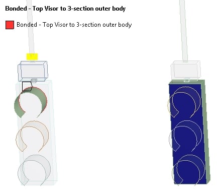
I added a Contact Tool under the Connections folder and find you have some far open contacts.
You have to fix those before your model will run.
RMB on the first Far Open and it will point you to that contact. Look at the definition: the face is on one fixture and the edge is on the other.
Fix these errors and then reply when you have all the contacts closed.
Regards, Peter
-
January 26, 2019 at 10:09 pm
Beny386
SubscriberHello Peter,
I will take at look at those errors. I'll reply when they are fixed.
Thank you
Beny
-
February 16, 2019 at 9:46 pm
Beny386
SubscriberHello Peter,
I managed to fix the far open contact errors that was occurring at the contact between the flat thin panel around the traffic light and the traffic light. According to the contact tool I ran. This bonded contact is contacted edge to edge. But I am still running up into an error.
Also, aside from the Static Structural model, I also included the Modal model in the attached file because I ran the modal analysis and it goes through with a solution but the solution is 0 hz frequencies for all three modes with strange mode shapes. When I previously ran the modal analysis I was obtaining an approximate frequency between 0.5 hz-0.7hz which is typical for this type of traffic signal assembly.
Please review the changes I made and see if you can spot anything that may be causing these errors.
Thank you
Beny
-
April 30, 2020 at 7:58 pm
peteroznewman
SubscriberDear edex,
Please open a New Discussion and enter your question in English. Then delete the post above.
Below is a Google Translate of the Turkish text above...
Hi
I want to show deformation for engine oil between the camshaft valve tappet and I melt the engine oil fluently and transfer it structurally temporarily, but I get the errors in the picture. Can you help me?
-
- You must be logged in to reply to this topic.


Boost Ansys Fluent Simulations with AWS
Computational Fluid Dynamics (CFD) helps engineers design products in which the flow of fluid components is a significant challenge. These different use cases often require large complex models to solve on a traditional workstation. Click here to join this event to learn how to leverage Ansys Fluids on the cloud, thanks to Ansys Gateway powered by AWS.

Earth Rescue – An Ansys Online Series
The climate crisis is here. But so is the human ingenuity to fight it. Earth Rescue reveals what visionary companies are doing today to engineer radical new ideas in the fight against climate change. Click here to watch the first episode.

Ansys Blog
Subscribe to the Ansys Blog to get great new content about the power of simulation delivered right to your email on a weekly basis. With content from Ansys experts, partners and customers you will learn about product development advances, thought leadership and trends and tips to better use Ansys tools. Sign up here.

- Solver Pivot Warning in Beam Element Model
- Saving & sharing of Working project files in .wbpz format
- Understanding Force Convergence Solution Output
- User manual
- An Unknown error occurred during solution. Check the Solver Output…..
- What is the difference between bonded contact region and fixed joint
- The solver engine was unable to converge on a solution for the nonlinear problem as constrained.
- whether have the difference between using contact and target bodies
- Colors and Mesh Display
- Defining rigid body and contact

-
7272
-
4248
-
2899
-
1374
-
1322

© 2025 Copyright ANSYS, Inc. All rights reserved.


