-
-
August 22, 2018 at 3:46 pm
PKS7
SubscriberHi
I am new to Fluent and am analyzing external flow of a CD nozzle. I did analytical calculations and came up with the BCs.
I was able to solve the first iteration with CFL as 5 and time step size (dt) as 1e-4 s. It wasn't the perfect solution as I monitored the net mass flow rate and it was close to zero but not exactly. Mass flow rate value stabilized over time.
To experiment, I kept the same BCs but reduced the throat size of the nozzle, effectively reducing the mass flow rate. But, now I'm having a hard time finding the right combination of CFL and dt. Is there a good way of coming up with these values than trial and error? Each run takes over 5 hrs just to show that the solution isn't correct.
I successfully ran both the analyses for internal flow under steady state conditions as a verification of BCs.
Additional details about my analysis -
- Model details - 2D geometry, inviscid model, Energy ON. Air as ideal gas.
- Minimum grid size - 5mm (about 350K elements, performed mesh dependence study on first problem and solution was independent of mesh size)
- Courant number condition - Currently running 5. Tried 1 as well but no luck. Both yielding high mass imbalance.
- Fixed time step or variable time step - Tried both. Fixed dt of 1e-3 and 1e-4 s. Currently running Adaptive time stepping and still seeing huge mass imbalance after 350 iterations with 50 iterations per step.
- Residual values - I have set residuals to 1e-6. Solution isn't converging at the end of 50 iterations of each step.
- Monitoring net mass flow rate between inlet and outlet as well as inlet mass flow rate. With fixed time steps values mentioned above, I obtained stable values for both but with mass imbalance of 2000 kg/s and inlet mass flow not matching my calculations. Adaptive time step did not yield stable flux values after 350 iterations. Running for 650 more iterations.
I even tried checking the box for - "Adjust Solver Defaults Based on Setup" which raised the CFL to 50. With a dt of 1e-4 s that led to Divergence. So, I have unchecked it again.
-
August 22, 2018 at 4:06 pm
Karthik Remella
AdministratorHello,
Courant number definition involves grid size, velocity scales and time step size. These three values are used to calculate what is popularly known as the CFL condition (please read about CFL condition on ANSYS Users and Theory Guide) for stable solution.
CFL condition: U * del_t / del_x < 1 (for a fully explicit scheme).
The best approach would be to take your minimum grid size and your velocity scale to calculate the minimum time step required using the above relationship.
About your current problem,
- Could you please elaborate a little on the boundary conditions?
- Are you solving a laminar or turbulent flow?
- What is your grid like? And please highlight the mesh quality metrics?
- If it is turbulent, which model are you using and what is your boundary layer thickness like?
- What discretization schemes are you using?
Please show some screenshots.
Thank you.
Best Regards,
Karthik
-
August 23, 2018 at 6:12 am
DrAmine
Ansys EmployeeI generally avoid interpreting results that is why I stick to theory:
The courant number when used with implicit formulation for a transient case is not the one which would influence time stepping but it would rather some diagonal dominance into the solution matrix. Is is sort of implicit under-relaxation for the iterative process to overcome nonlinearities and to enhance stability. Implicit schemes are unconditionally stable. For the density based solver we are working with dual time stepping approach. More details can be found in the theory guide.
You said you are now using Implicit Formulation: the time step size is not steered by the CFL under solution controls as both inputs are required for the dual time formulation (pseudo-time marching).
But here I am curious to know: From pictures is not clear for me how you have created that pressure Inlet: Can you check if you have reversal flow on your pressure inlet
-
August 24, 2018 at 6:20 am
DrAmine
Ansys EmployeeSo you have definitely reversal flow. Do you think this is physical?
Is your pressure Inlet set as interior I cannot figure out how you are modeling that part as this is not straightforward to set.
Here a Workshop created by Raef which you might look into it:
-
September 1, 2018 at 3:59 pm
PKS7
SubscriberHi
I was under the impression that flow reversal was caused as the domain is not big enough, i.e., outlet is not too far from the inlet. Is that not the case?
I have been able to solve other problems despite of receiving the same flow reversal warning.
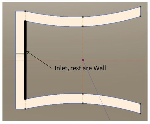
I have modeled the nozzle as a 2D sketch as shown below with the inlet highlighted.
-
September 1, 2018 at 4:03 pm
PKS7
Subscriber
Hello,
Courant number definition involves grid size, velocity scales and time step size. These three values are used to calculate what is popularly known as the CFL condition (please read about CFL condition on ANSYS Users and Theory Guide) for stable solution.
CFL condition: U * del_t / del_x < 1 (for a fully explicit scheme).
The best approach would be to take your minimum grid size and your velocity scale to calculate the minimum time step required using the above relationship.
About your current problem,
- Could you please elaborate a little on the boundary conditions?
- Are you solving a laminar or turbulent flow?
- What is your grid like? And please highlight the mesh quality metrics?
- If it is turbulent, which model are you using and what is your boundary layer thickness like?
- What discretization schemes are you using?
Please show some screenshots.
Thank you.
Best Regards,
Karthik
If I use Courant No. as 1, and my min edge length is 5 mm and initial inlet velocity is about 84 m/s, so dt < (1*5e-3/84) = 6e-5 s. Is this what you were suggesting earlier? -
September 4, 2018 at 10:30 am
Rob
Ansys EmployeeLooks about right, I'd probably start with 1e-5s and see how it runs.
-
September 4, 2018 at 9:53 pm
Karthik Remella
AdministratorHello,
Yes, you are correct with this calculation. This is what I was suggesting you do to estimate the minimum time step for your simulation. Please let us know what you find.
Thank you.
Best Regards,
Karthik
-
- You must be logged in to reply to this topic.


Boost Ansys Fluent Simulations with AWS
Computational Fluid Dynamics (CFD) helps engineers design products in which the flow of fluid components is a significant challenge. These different use cases often require large complex models to solve on a traditional workstation. Click here to join this event to learn how to leverage Ansys Fluids on the cloud, thanks to Ansys Gateway powered by AWS.

Earth Rescue – An Ansys Online Series
The climate crisis is here. But so is the human ingenuity to fight it. Earth Rescue reveals what visionary companies are doing today to engineer radical new ideas in the fight against climate change. Click here to watch the first episode.

Ansys Blog
Subscribe to the Ansys Blog to get great new content about the power of simulation delivered right to your email on a weekly basis. With content from Ansys experts, partners and customers you will learn about product development advances, thought leadership and trends and tips to better use Ansys tools. Sign up here.

- Floating point exception in Fluent
- What are the differences between CFX and Fluent?
- Heat transfer coefficient
- Difference between K-epsilon and K-omega Turbulence Model
- Getting graph and tabular data from result in workbench mechanical
- The solver failed with a non-zero exit code of : 2
- Suppress Fluent to open with GUI while performing in journal file
- Mesh Interfaces in ANSYS FLUENT
- Time Step Size and Courant Number
- error: Received signal SIGSEGV

-
7272
-
4248
-
2899
-
1374
-
1322

© 2025 Copyright ANSYS, Inc. All rights reserved.


