-
-
October 29, 2017 at 2:58 pm
peteroznewman
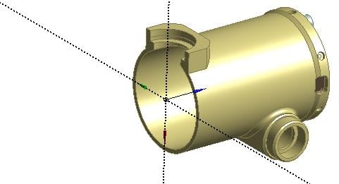
SubscriberIf we want to have a half model of this…
In DM, click Tools, Symmetry then select the Plane. Usually the geometry is a Full Model.
(Sometimes only one side of the part has been created before a mirror feature completes the part. In this case, then the Model Type is Partial Model.)
Generate and this is the result.
If you want the other half, you have to create a plane where the Z axis points to the half you want to keep. In this case I created Plane4.
In Mechanical, build a model and get a solution.
In Workbench, Tools, Options, Appearance, turn on Beta Options (one time configuration).
In Mechanical, click on the Symmetry item to get the details window.
Set Num Repeat to 2 and Method to Half and put 1e-3 into ?Z.
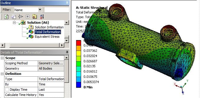
Click on the Total Deformation and you will have the symmetry expanded.
-
November 6, 2017 at 5:30 pm
-
June 13, 2018 at 2:22 pm
Adisa
SubscriberPeter,
Thank you. I do symmetry of a beam, but in results do not show the other side of beam. And value of displacement is of half beam, i need to divide a displacement with 2 for getting a displacement of whole beam.
-
June 13, 2018 at 5:20 pm
-
June 14, 2018 at 8:57 am
Adisa
SubscriberPeter,
I already included the Beta Options, but I thought that the results will be of whole part.
OK, thank you.
-
June 14, 2018 at 10:47 am
peteroznewman
SubscriberAdisa,
Yes, the results will be the whole part. When I opened your file, there was only 2 elements through the width of the part in the symmetry direction, then I turned on Beta options and now in the results I see 4 elements through the width of the part.
Cheers,
Peter -
April 4, 2019 at 1:57 pm
amnteno1
SubscriberHello,
Here I have attached a very simple model, where I wanted to check out using symmetry as Peter described (I didn't get how to attach models here in the Forum, so there is a link to a cloud, where I saved it as a wbpz file).
I think, that I have followed Peters description: I created a model and applied two symmetry planes in DM, so now I have a quarter of my original object. I applied a displacement and that worked well. However, I was not able to visualize the full model. Beta Options are turned on, and I put a value of 0.001 at Delta Z (By the way, why do we have to do so? Seems a bit random to me. And always for Delta Z? Or depending on my symmetry plane sometimes also on Delta y or Delta x?)
Then I go to the solution again, but there is still only a quarter of the modell. Has anyone some helpful hints, why I can't visualize the full model?
Regards,
Stephan
-
April 5, 2019 at 2:57 am
-
April 5, 2019 at 8:12 am
amnteno1
SubscriberThank you! My error was to use the global coordinate System instead of the planes created by the symmetry tool (in my case, the Global XY and YZ- Planes are the geometrically the same as the symmetry planes, so I got a little confused...).
I am still wondering about the 1.e-003 at Delta Z. I mean, I do it, and it works fine, but I don't really know why I'am doing it. Has anyone an explanation for that?
-
April 6, 2019 at 2:29 pm
peteroznewman
SubscriberThe need to put in a small delta is a hack for incomplete development of the software. That is why this feature is a Beta option, it's not finished. Maybe the developers will figure out how to make it work with the default 0. Maybe the feature will will move out of the Beta category.
-
September 26, 2019 at 12:30 pm
-
September 26, 2019 at 3:08 pm
peteroznewman
SubscriberI can't see the Triad in the screen shots above. It looks like the X axis is normal to the plane of symmetry so the 1e-3 should be in the delta X field but maybe it should be -1e03 depending on which way the X axis is pointing. You have 1e-3 in the delta Z field, which is wrong. You also should change Method from Full to Half.
-
September 26, 2019 at 8:53 pm
-
September 26, 2019 at 10:59 pm
peteroznewman
SubscriberThe stress and strain are defined by the deformation. The symmetry just makes it so the gradient of stress normal to the centerplane is zero.
-
September 26, 2019 at 11:27 pm
mekafime
SubscriberHi peter
It means that to graph, apart from the deformation, stress and strain should also be multiplied by two (for the previous example that is half of the solid)
Thanks!
-
September 27, 2019 at 3:08 am
peteroznewman
SubscriberDeformation is local, so is not multiplied by two when 1/2 symmetric model is solved.
Half the force is applied to half the model to get the same local deformation that would occur if the full force was applied to the full model.
That means, when you get reaction force on a half model, you have to multiply it by 2 to get the value for the full model.
-
November 22, 2019 at 6:29 pm
skpb
Subscriberhello peter
In symmetry Graphical Expansion, why we need Num repeats, shouldn't be always 2 ? Or what is really behind that?
-
November 23, 2019 at 12:53 am
peteroznewman
SubscriberIf you had cyclic symmetry, and modeled a 10 degree slice, then you would need 36 repeats to make a full model.
-
November 23, 2019 at 5:27 am
-
October 2, 2020 at 1:50 pm
javiarredondo
SubscriberHello Peter, I have a question regarding symmetry too. I am modeling a reinforced concrete pole, when I applied the simmetry to the full model I noticed reinforcement didn´t dissapear in the simmetry plane, like it is not taken into account. In mechanical, using Ansys 2020 I give the lines the Reinforcement property. If I apply simmetry, would the reinforcement be taken into account in the half not shown?n -
October 2, 2020 at 3:15 pm
peteroznewman
SubscribernIt would be best to trim each line to the symmetry plane and apply symmetry BCs to the vertices on that plane. For example, if the symmetry plane is XZ and Y is normal, you would apply Displacement Y = 0, Rotation X = 0, and Rotation Z = 0 to every line body vertex on that plane. This is the same for a shell element edge that is cut by the symmetry plane. Solid elements have no rotational DOF at the nodes, so the only BC is Displacement Y = 0.nOnce you have symmetry properly defined, the model behaves as if there was a mirror image of the structure on the other side of the plane, enforcing the correct displacements on the half you can see.nIn Ansys2020 R2, when you apply Reinforcement property to the line bodies in Mechanical, the nodes on the line bodies automatically connect with the nodes on the adjacent solid elements.n -
October 4, 2020 at 8:19 pm
javiarredondo
SubscriberThanks Peter! Very clear answer, I replied you on my post too! Take a look whenever you can n
-
- You must be logged in to reply to this topic.


Boost Ansys Fluent Simulations with AWS
Computational Fluid Dynamics (CFD) helps engineers design products in which the flow of fluid components is a significant challenge. These different use cases often require large complex models to solve on a traditional workstation. Click here to join this event to learn how to leverage Ansys Fluids on the cloud, thanks to Ansys Gateway powered by AWS.

Earth Rescue – An Ansys Online Series
The climate crisis is here. But so is the human ingenuity to fight it. Earth Rescue reveals what visionary companies are doing today to engineer radical new ideas in the fight against climate change. Click here to watch the first episode.

Ansys Blog
Subscribe to the Ansys Blog to get great new content about the power of simulation delivered right to your email on a weekly basis. With content from Ansys experts, partners and customers you will learn about product development advances, thought leadership and trends and tips to better use Ansys tools. Sign up here.

- How to work with STL file?
- Rotate tool in ANSYS Design Modeler
- section plane
- Using Symmetry in DesignModeler and Expanding the Results
- ANSYS FLUENT – Operation would result in non manifold bodies
- drawing a geometry by importing a table of points
- material properties
- Geometry scaling
- Coordinates orientation
- “contact pair has no element in it.” how to resolve this problem

-
7272
-
4248
-
2899
-
1374
-
1322

© 2025 Copyright ANSYS, Inc. All rights reserved.


